Connect Brushless Motors to Arduino Through ESC’s (ArduinoQuad)

Brushless motors come in handy when your project requires high RPM and low maintenance. A fantastic video by 000Plasma000 explains the properties of brushless motors very concisely.

UPDATE: WordPress is changing some of my code blocks to ‘amp’ and I haven’t yet found a way to fix this. For further guidance (although it would be a good exercise to infer), head over to my github repository.

Things You will need

Hardware:

  • Brushless DC motors
  • Electronic Speed Controllers (ESC’s). Preferably 30 AMP SimonK ESC’s
  • Lithium Polymer (LiPo) Battery. These are essentially the same batteries used by FPV drones or planes or RC cars.
  • Power Distribution Board (optional, if you want to connect more than one brushless motor to the Arduino)

Software:

  • Arduino IDE

Making the connections

For all intents and purposes, you will be treating an ESC+Brushless motor combo as if it were a servo. You’ll see this application in action soon, but for now, follow the diagram and instructions to connect the Motor to the ESC and the ESC to the Arduino.

ESC DIAG.jpg

The ground and power wires of the Motor can be interchanged with each other in plugging into the ground and power slots on the ESC. It doesn’t matter where these wires go, as long as they stay on the outside, switching them will just switch the direction. The signal wire must connect with the middle wire on the ESC as this transmits the signal. Different motors and ESC’s have different arrangements for this, so it is up to you to figure out which wire carries the signal on both the ESC and Motor so you can mess about with the other two any way you like.

f769f4fb7da44324

There will be 3 thin wires from the ESC. These will be differently colored, but one of these will be for power input, one for the Signal and one that goes to ground. You must research the color coding of your wires and then accordingly plug the signal wire into PWM port 9 and the Ground wire to GND. DO NOT PLUG THE POWER INPUT WIRE INTO THE ARDUINO, you may fry your computer’s USB port along with the Arduino.

Arduino Code

#include <Servo.h>

int value = 0; // set values you need to zero

Servo firstESC, secondESC; //Create as many as Servo objects as you want. You can control 2 or more Servos at the same time

void setup() {

  firstESC.attach(9);    // attached to pin 9 I just do this with 1 Servo
  Serial.begin(9600);    // start serial at 9600 baud (can change this)

}

void loop() {

//First connect your ESC WITHOUT Arming. Then Open Serial and follow Instructions

  firstESC.write(value);

  if(Serial.available())
    value = Serial.parseInt();    // Parse an Integer from Serial

}

As is evident, we’re treating the ESC as if it were a servo object. You can add more servo objects if you like, just connect them to a breadboard and to more PWM’s. This code will allow you to send a value through the serial monitor on your Arduino IDE, and control the speed of your ESC’s accordingly

My Setup

Start by connecting the ESC to the battery. You should hear a little beep. Then, connect the USB to the Arduino and load the program. You should hear another beep. Nevertheless, this all depends on what kind of ESC you have. Mine had black, white and red , White was for the signal, so that went to PWM port 9. Black was for ground so that went to ground.

Brushless Motor’s in Action

The following video show’s my brushless motors in action. I vary the serial input from 10 to around 150, and as expected, higher values result in higher RPM.

The right way to connect an HC-05 Bluetooth module to an Arduino (Running Linux Ubuntu)

The HC-05 Bluetooth module is extremely useful for wireless communication and will last long if you know how to use it correctly.

UPDATE: WordPress is changing some of my code blocks to ‘amp’ and I haven’t yet found a way to fix this. For further guidance (although it would be a good exercise to infer), head over to my github repository.

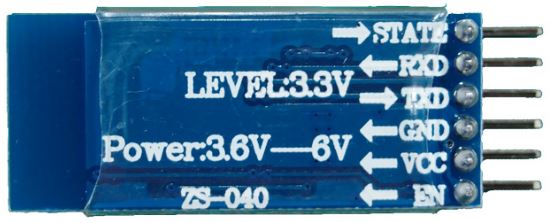
The first mistake people make when rushing to get the HC-05 module is when they connect the TX from the Arduino directly to the RX in the Hc-05. However, the TX on the Arduino transmits a 5 volt (5v) signal, whereas the RX  on the Hc-05 accepts only upto 3.3 volts (3v). Here’s a picture for proof:

Hc-05


Notice how the RX (same as RXD) has Level 3.3V. Any more and you could risk blowing up your Bluetooth module!

Breadboarding

So start off by getting it wired on your breadboard the following way. The resistors used in this positioning allow 5v to drop to 3.3v , allowing you to communicate with your bluetooth module safely.

HC-05 Tutorial.jpg

At this point, you should only care about those 4 pins on the Hc-05. Don’t worry about the rest. (State and EN)

For the resistor setup, understand the following: The easiest way to go about this is by picking 3 resistors of the same type. I would suggest something in the 1K – 10K range. To understand more about how exactly this voltage divider works, visit this website .

Install Blueman Bluetooth Manager (for Ubuntu 14.04)

This is a useful bluetooth manager and will allow the HC-05 to connect to a comm port on your laptop with ease. Just open terminal and type in the following two lines of code:

sudo apt-get update
sudo apt-get install blueman


Install CuteCom (for Ubuntu 14.04 )

If you’re running Ubuntu, you should install Cutecom. It will allow you to read from your connected comm port. Just type in the following two lines of code in the Terminal:

sudo apt-get update
sudo apt-get install cutecom

Arduino Code

This is the .ino code you should compile. You can either copy paste this into the Arduino IDE or download the .ino file below itself.

int counter =0;
char INBYTE;
void setup() {
  pinMode(13, OUTPUT);
  Serial.begin(9600);
  delay(50);
}

void loop() {
  counter++;
  Serial.println("Press 1 to turn on LED and 0 to turn off ");
  while (true){
    if (Serial.available()){
      break;
    }
  }
  INBYTE = Serial.read();
  if (INBYTE == '0'){
    digitalWrite(13, LOW);

  }
  if (INBYTE == '1'){
    digitalWrite(13, HIGH);
  }
  Serial.println(counter);
  delay(50); // wait half a sec
}

Testing the Module

I will cover troubleshooting in another tutorial, but at this point, following these instructions should get everything working fine.

  1.  Remove the RX and TX connection from the arduino. This is temporary. Do not remove the wire entirely, just disconnect the end’s that are connected to the Arduino’s RX and TX ports.
  2. Download the following tester code or copy paste it from above: BLUETOOTH_TEST.ino
  3. Compile this code onto the Arduino.
  4. Disconnect the USB from the Arduino (very important).
  5. Attach a 9V battery with a barrel jack to the Arduino.
  6. Open Bluetooth Manager and walk yourself through setting up the device.
    You should see something like this:

This slideshow requires JavaScript.

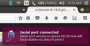
7.Once you’re done setting up, this notification should pop on the screen. Take note of the rfcomm number. These will be of the form /dev/rfcomm0 or /dev/rfcomm1 etc.

SerialPOrt

8.Open a Terminal

      9.Type in cutecom

dhruv@DhruvROS: ~_008

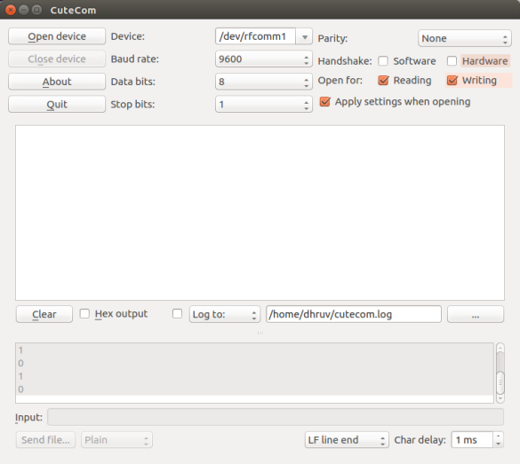
  1. Where it says Device: , change the name to whichever rfcomm port your HC-05 is connected to.CuteCom_009
  2. Set the Baud rate to 9600
  3. Click Open Device 
  4. You should see the text box below open up.
  5. Press 1 to turn on LED and 0 to Turn it off.