The Real Roboticist (lesson 2): Installing ROS on your Ubuntu LTS 14.04

Introduction

Here you’ll be installing ROS indigo (which is just a distribution of ROS, like Ubuntu is a distribution of Linux). I recommend ROS indigo because it is the most stable version to date and will have support until 2019. It also supports the latest version of Ubuntu.

Setup your sources.list

Setup your computer to accept software from packages.ros.org. ROS Indigo ONLY supports Saucy (13.10) and Trusty (14.04) for Debian packages.

sudo sh -c 'echo "deb http://packages.ros.org/ros/ubuntu
(lsb_release -sc) main" > /etc/apt/sources.list.d/ros-latest.list'

 Set up your keys

sudo apt-key adv --keyserver hkp://ha.pool.sks-keyservers.net --recv-key 0xB01FA116

You can try the following command by adding :80 if you have gpg: keyserver timed out error

sudo apt-key adv –keyserver hkp://ha.pool.sks-keyservers.net:80 –recv-key 0xB01FA116

Installation

First, make sure your Debian package index is up-to-date:

sudo apt-get update

Now for the magic line

sudo apt-get install ros-indigo-desktop-full

If doing all that returns an error, try copy pasting this entire section into your terminal.

sudo sh -c 'echo "deb http://packages.ros.org/ros/ubuntu trusty main" > /etc/apt/sources.list.d/ros-latest.list'

wget https://raw.githubusercontent.com/ros/rosdistro/master/ros.key -O - | sudo apt-key add -

sudo apt-get update

sudo apt-get install ros-indigo-desktop-full

Initialize rosedp

The ROS system may depend on software packages that are not loaded initially. These software packages external to ROS are provided by the operating system. The ROS environment command rosdep is used to download and install these external packages. It’s kind of like the way you use sudo apt-get install, except since ROS is a different operating system, you use this.
Type the following command:

sudo rosdep init
rosdep update

Setup ROS environment

source /opt/ros/indigo/setup.bash

Sometimes it’s easier if the variables are automatically added to your sessions every time a new shell is launched. Do so by typing the following command into terminal.

echo "source /opt/ros/indigo/setup.bash" >> ~/.bashrc
source ~/.bashrc

Rosinstall

This is the kind of like the terminal, except for ROS packages.

sudo apt-get install python-rosinstall

For more help and troubleshooting, visit the official ROS website and for problems with setting up the environment, try http://wiki.ros.org/ROS/Tutorials/InstallingandConfiguringROSEnvironment.

Connect Brushless Motors to Arduino Through ESC’s (ArduinoQuad)

Brushless motors come in handy when your project requires high RPM and low maintenance. A fantastic video by 000Plasma000 explains the properties of brushless motors very concisely.

UPDATE: WordPress is changing some of my code blocks to ‘amp’ and I haven’t yet found a way to fix this. For further guidance (although it would be a good exercise to infer), head over to my github repository.

Things You will need

Hardware:

  • Brushless DC motors
  • Electronic Speed Controllers (ESC’s). Preferably 30 AMP SimonK ESC’s
  • Lithium Polymer (LiPo) Battery. These are essentially the same batteries used by FPV drones or planes or RC cars.
  • Power Distribution Board (optional, if you want to connect more than one brushless motor to the Arduino)

Software:

  • Arduino IDE

Making the connections

For all intents and purposes, you will be treating an ESC+Brushless motor combo as if it were a servo. You’ll see this application in action soon, but for now, follow the diagram and instructions to connect the Motor to the ESC and the ESC to the Arduino.

ESC DIAG.jpg

The ground and power wires of the Motor can be interchanged with each other in plugging into the ground and power slots on the ESC. It doesn’t matter where these wires go, as long as they stay on the outside, switching them will just switch the direction. The signal wire must connect with the middle wire on the ESC as this transmits the signal. Different motors and ESC’s have different arrangements for this, so it is up to you to figure out which wire carries the signal on both the ESC and Motor so you can mess about with the other two any way you like.

f769f4fb7da44324

There will be 3 thin wires from the ESC. These will be differently colored, but one of these will be for power input, one for the Signal and one that goes to ground. You must research the color coding of your wires and then accordingly plug the signal wire into PWM port 9 and the Ground wire to GND. DO NOT PLUG THE POWER INPUT WIRE INTO THE ARDUINO, you may fry your computer’s USB port along with the Arduino.

Arduino Code

#include <Servo.h>

int value = 0; // set values you need to zero

Servo firstESC, secondESC; //Create as many as Servo objects as you want. You can control 2 or more Servos at the same time

void setup() {

  firstESC.attach(9);    // attached to pin 9 I just do this with 1 Servo
  Serial.begin(9600);    // start serial at 9600 baud (can change this)

}

void loop() {

//First connect your ESC WITHOUT Arming. Then Open Serial and follow Instructions

  firstESC.write(value);

  if(Serial.available())
    value = Serial.parseInt();    // Parse an Integer from Serial

}

As is evident, we’re treating the ESC as if it were a servo object. You can add more servo objects if you like, just connect them to a breadboard and to more PWM’s. This code will allow you to send a value through the serial monitor on your Arduino IDE, and control the speed of your ESC’s accordingly

My Setup

Start by connecting the ESC to the battery. You should hear a little beep. Then, connect the USB to the Arduino and load the program. You should hear another beep. Nevertheless, this all depends on what kind of ESC you have. Mine had black, white and red , White was for the signal, so that went to PWM port 9. Black was for ground so that went to ground.

Brushless Motor’s in Action

The following video show’s my brushless motors in action. I vary the serial input from 10 to around 150, and as expected, higher values result in higher RPM.

The right way to connect an HC-05 Bluetooth module to an Arduino (Running Linux Ubuntu)

The HC-05 Bluetooth module is extremely useful for wireless communication and will last long if you know how to use it correctly.

UPDATE: WordPress is changing some of my code blocks to ‘amp’ and I haven’t yet found a way to fix this. For further guidance (although it would be a good exercise to infer), head over to my github repository.

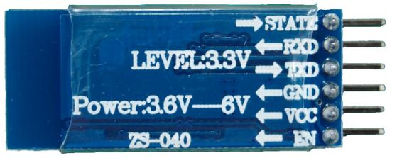
The first mistake people make when rushing to get the HC-05 module is when they connect the TX from the Arduino directly to the RX in the Hc-05. However, the TX on the Arduino transmits a 5 volt (5v) signal, whereas the RX  on the Hc-05 accepts only upto 3.3 volts (3v). Here’s a picture for proof:

Hc-05


Notice how the RX (same as RXD) has Level 3.3V. Any more and you could risk blowing up your Bluetooth module!

Breadboarding

So start off by getting it wired on your breadboard the following way. The resistors used in this positioning allow 5v to drop to 3.3v , allowing you to communicate with your bluetooth module safely.

HC-05 Tutorial.jpg

At this point, you should only care about those 4 pins on the Hc-05. Don’t worry about the rest. (State and EN)

For the resistor setup, understand the following: The easiest way to go about this is by picking 3 resistors of the same type. I would suggest something in the 1K – 10K range. To understand more about how exactly this voltage divider works, visit this website .

Install Blueman Bluetooth Manager (for Ubuntu 14.04)

This is a useful bluetooth manager and will allow the HC-05 to connect to a comm port on your laptop with ease. Just open terminal and type in the following two lines of code:

sudo apt-get update
sudo apt-get install blueman


Install CuteCom (for Ubuntu 14.04 )

If you’re running Ubuntu, you should install Cutecom. It will allow you to read from your connected comm port. Just type in the following two lines of code in the Terminal:

sudo apt-get update
sudo apt-get install cutecom

Arduino Code

This is the .ino code you should compile. You can either copy paste this into the Arduino IDE or download the .ino file below itself.

int counter =0;
char INBYTE;
void setup() {
  pinMode(13, OUTPUT);
  Serial.begin(9600);
  delay(50);
}

void loop() {
  counter++;
  Serial.println("Press 1 to turn on LED and 0 to turn off ");
  while (true){
    if (Serial.available()){
      break;
    }
  }
  INBYTE = Serial.read();
  if (INBYTE == '0'){
    digitalWrite(13, LOW);

  }
  if (INBYTE == '1'){
    digitalWrite(13, HIGH);
  }
  Serial.println(counter);
  delay(50); // wait half a sec
}

Testing the Module

I will cover troubleshooting in another tutorial, but at this point, following these instructions should get everything working fine.

  1.  Remove the RX and TX connection from the arduino. This is temporary. Do not remove the wire entirely, just disconnect the end’s that are connected to the Arduino’s RX and TX ports.
  2. Download the following tester code or copy paste it from above: BLUETOOTH_TEST.ino
  3. Compile this code onto the Arduino.
  4. Disconnect the USB from the Arduino (very important).
  5. Attach a 9V battery with a barrel jack to the Arduino.
  6. Open Bluetooth Manager and walk yourself through setting up the device.
    You should see something like this:

This slideshow requires JavaScript.

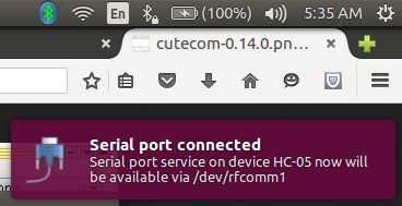
7.Once you’re done setting up, this notification should pop on the screen. Take note of the rfcomm number. These will be of the form /dev/rfcomm0 or /dev/rfcomm1 etc.

SerialPOrt

8.Open a Terminal

      9.Type in cutecom

dhruv@DhruvROS: ~_008

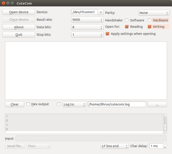
  1. Where it says Device: , change the name to whichever rfcomm port your HC-05 is connected to.CuteCom_009
  2. Set the Baud rate to 9600
  3. Click Open Device 
  4. You should see the text box below open up.
  5. Press 1 to turn on LED and 0 to Turn it off.

Color trackbar/slider using OpenCV Python

Original vs threeshBy the end of this post, you’ll have made a pretty basic HSV color trackbar/slider that filters out a range of colors, leaving you with the range of colors that you want to identify. HSV stands for ‘Hue, Saturation, Value’. It is composed of 3 separate values that determine the range of colors that you’d want to find.

If you just want the code, follow this link to my github

https://github.com/botforge/ColorTrackbar/blob/master/HSV%20Trackbar.py

Prerequisites

This tutorial assumes you have some degree of proficiency with Python and have dabbled around with OpenCV. If you haven’t touched OpenCV ever, this tutorial still has links to whatever you may need to know to complete writing this code.

1. Creating Trackbars

OpenCV has a pretty good tutorial on creating and reading multiple trackbars, but it digresses from the application we intend to use it for. Carefully reading the following section should suffice.

Don’t worry if you don’t get some of it, I’ll explain the important functions soon.

#import the necessary packages
import cv2
import numpy as np
#'optional' argument is required for trackbar creation parameters
def nothing:
pass

#Capture video from the stream
cap = cv2.VideoCapture(0)
cv2.namedWindow('Colorbars') //Create a window named 'Colorbars'

#assign strings for ease of coding
hh='Hue High'
hl='Hue Low'
sh='Saturation High'
sl='Saturation Low'
vh='Value High'
vl='Value Low'
wnd = 'Colorbars'
#Begin Creating trackbars for each
cv2.createTrackbar(hl, wnd,0,179,nothing)
cv2.createTrackbar(hh, wnd,0,179,nothing)
cv2.createTrackbar(sl, wnd',0,255,nothing)
cv2.createTrackbar(sh, wnd,0,255,nothing)
cv2.createTrackbar(vl, wnd,0,255,nothing)
cv2.createTrackbar(vh, wnd',0,255,nothing)

You may be wondering what the parameters of the cv2.createTrackbar() function are. The OpenCV documentation is the best place for a comprehensive explanation, but I’ll give you one more specific to the problem we’re solving.

So the parameters are as follows:

cv2.createTrackbar(trackbarname, windowname, minimum, maximum, argument)

We assigned our trackbar names in lines 13-18 and our window name in line 19. The minimum position of the trackbar for all instances is 0. In simpler terms, when you slide the slider, it won’t go below a value of 0 as no HSV values are negative. The maximum  position varies. For the Hue values it goes from 0-180, and for Saturation and Val, it goes from 0-255.

There’s no need to concern yourself with why those numbers were chosen, but if your interested, there are a bunch of books by O’Reilly on safaribooksonline.com to learn about the mathematics behind computer vision.

2. Reading and processing Trackbars

Here’s where the real stuff comes in. As usual, don’t fret if you don’t get the code, but try reading and understanding as much as you can.

#begin our 'infinite' while loop
while(1):
    #read the streamed frames (we previously named this cap)
    _,frame=cap.read()

    #it is common to apply a blur to the frame
    frame=cv2.GaussianBlur(frame,(5,5),0)

    #convert from a BGR stream to an HSV stream
    hsv=cv2.cvtColor(frame, cv2.COLOR_BGR2HSV)

All we did here was read the stream we previously assigned as cap.

Reading  the frame using the x.read() function returns a tuple. You can ignore the first value for now, and call the second value frame. This frame variable is actually an array of values. Each element of this array contains BGR (Blue, Green, Red) values. Concretely, each element is a pixel.

We also introduced a Gaussian Blur. This is commonly applied in order to reduce single pixel anomalies while searching the array. Read more about the Gaussian blur function here, but for the sake of simplicity, just remember that the first parameter is the array of pixels you receive from cap.read(), and the other numbers can generally remain untouched. 

The conversion between BGR to HSV is analogous to the conversion between mp3 and wav for your music files. You’re essentially converting the data in the frame so it becomes readable in a different way. That’s what the cv2.cvtColor() function does. You then name your new array ‘hsv


    #read trackbar positions for each trackbar
    hul=cv2.getTrackbarPos(hl, wnd)
    huh=cv2.getTrackbarPos(hh, wnd)
    sal=cv2.getTrackbarPos(sl, wnd)
    sah=cv2.getTrackbarPos(sh, wnd)
    val=cv2.getTrackbarPos(vl, wnd)
    vah=cv2.getTrackbarPos(vh, wnd)

    #make array for final values
    HSVLOW=np.array([hul,sal,val])
    HSVHIGH=np.array([huh,sah,vah])

#create a mask for that range
mask = cv2.inRange(hsv,HSVLOW, HSVHIGH)

The stuff above is pretty self explanatory. You read the trackbars with cv2.getTrackbarPos() and assign them to variables (you can name them anything).

In lines 10-11, your final frame shouldn’t show the whole frame, it should only show the range specified by your trackbar. To do that, you have to make a numpy array with the lower HSV values, and one with your higher HSV values. You then have to create a mask to apply this range to the frame. That’s what cv2.inRange()  does.

    res = cv2.bitwise_and(frame,frame, mask =mask)

    cv2.imshow(wnd, res)
    k = cv2.waitKey(5) && 0xFF
    if k == ord('q'):
        break

cv2.destroyAllWindows()

The cv2.bitwise_and function allows you to display your mask (the HSV image with the filtered range) back onto your initial frame. cv2.imshow(takes 2 parameters, namely, window name and image array. We’ll keep our initial window name, and we’ll choose to display the res array, as that contains the filtered array displayed on the initial frame.

Lines 4-6 just allows you to quit the whole process by pressing ‘q’.

That’s about it. Now dabble around with the trackbars to find your desired color range. Next, Learn how to track a filtered object across the screen.